Introduction
We continue the previous post by looking in more detail at the PWM hardware on the Pico and look at how we can use it to drive a MOSFET switch and power transformer.
PWM and the Pico
The Pico has 8 PWM "slices" (identical functional units) that can be used either to generate PWM signals or for frequency measurement. In this case we don't need the latter. Each slice has two "channels" (possible outputs): both share the same frequency, but they can have individual duty cycles. There is a fixed assignment of hardware pins to slices and channels: if you configure a specific pin for PWM, it will always map to the same channel in the same slice.
Each slice has a counter that counts up to a programmable limit value ("wrap"), at which it (normally) wraps back to 0. Each channel has a threshold register ("level"): when the slice counter is below the threshold, the channel outputs a logic "1" after which the output transitions to "0" until the counter wraps (it's possible to invert this logic).
The following code snippet generates a series of PWM signals at different frequencies and different duty cycles.
1 2 3 4 5 6 7 8 9 10 11 12 13 14 15 16 17 18 19 20 21 22 23 24 25 26 27 28 29 30 31 32 33 34 35 36 | #include "pico/stdlib.h" #include <stdio.h> #include "hardware/pwm.h" #define PWM_PIN 5 int main() { int limits[3] = { 512, 1024, 2048 }; // Maximum count for PWM slice int duty[5] = { 16, 12, 8, 4, 2 }; // Divisors for maximum count used to select different duty cycles stdio_init_all(); gpio_set_function(PWM_PIN, GPIO_FUNC_PWM); uint slice_num = pwm_gpio_to_slice_num(PWM_PIN); while (1) { for (int l = 0 ; l < 3 ; l++) { for (int c = 0 ; c < 5 ; c++) { int k = limits[l] / duty[c]; printf ("TOP: %d, THRESHOLD: %d\n", limits[l], k); pwm_set_wrap(slice_num, limits[l]); pwm_set_gpio_level(PWM_PIN, k); pwm_set_enabled(slice_num, true); sleep_ms(5000); } } tight_loop_contents(); } } |
In line 5, we choose an output pin for the PWM signal. At line 9 we choose three possible different signal frequencies for the output signal by setting the maximum number to which the PWM slice will count - because the default clock has a frequency of around 125MHz, these correspond roughly to 250kHz, 125kHz and 60kHz. In line 10 we choose different duty cycles - the threshold at which the PWM slice switches off is calculated by dividing the maximum count by these numbers: the maximum duty cycle is 50% (dividing by 2). In line 14 we configure the selected pin for PWM mode and at line 15 we calculate the hardware PWM slice to which the pin corresponds.
We then run through each of the 3 frequencies configuring the PWM hardware to generate the output signal of the chosen frequency with each of 5 different duty cycles.
There are (confusingly) several different ways of managing the PWM hardware, but I find the method shown to be the most straightforward. In line 27 we set the "wrap" value for the PWM slice using one of the values from limits. We set the threshold "level" at which the signal switches in line 28. The function pwm_set_gpio_level selects the appropriate PWM slice and channel which makes it easier to alter the pin number without altering code. Finally, line 29 starts the particular PWM slice (it's OK to call if the slice is already running) and it runs autonomously, generating the output signal even while the CPU is sleeping.
It is possible to generate an interrupt whenever the PWM counter reaches its limit, but it's not necessary and if the PWM hardware is running at a high frequency, it is almost certainly not desirable either.
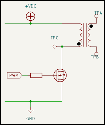
We need to take into account the current capablilities of the GPIO pins. There's a potentially short, but significant, inrush current owing to the MOSFET's gate-source capacitance when the GPIO pin goes high, so it's best to connect a smallish resistor between the PWM pin and the MOSFET gate to limit this. Too high a value and MOSFET will never turn on, but a value around 270R will probably work.
Note that to achieve fast swtiching performance, higher drive currents (and additional driver circuits) may be required in other circumstances. The MOSFET I used was an IRL540 as it was available. I used two of the windings on the WE-FLEX transformer.
When wired up as shown in the circuit diagram, we can see the signal AT TPC (red) and also the transformer output signal between TPA and TPB (blue) - there's a bit of horizontal drift where the 'scope had some trouble triggering accurately:
Two things are fairly obvious: firstly that as the duty cycle of the input signal increases, the range of the output voltage increases at all frequencies; secondly, the frequency of the input signal affects the output voltage range for the same duty cycle.
Even though the transformer ratio in this case is 1:1, the output voltage excursion can be significantly greater than the input, so it's looking like we may have the basis of a circuit that can significantly boost the input voltage.
Note, however, that the diode is missing from the secondary circuit at this stage, so the secondary is conducting at the same time as the primary. We'll see later how the waveforms change when the diode is in place.
In the next post, we'll look at how we can measure the output voltage which we will need ultimately to provide a regulated supply.

Comments
Post a Comment