Introduction
In the first part, we looked at candidate designs; in the second part we looked at a concrete implementation. In the final part of this series, we'll briefly cover the final construction of the prototype.
Power and Grounding
A couple of other posts cover some of the considerations relating to phantom power and gounding. As discussed in the previous posts, the DC-DC converter that supplies the phantom power is right at the edge of its operating range when supplying 48V, so I opted to settle for a slightly lower supply voltage (around 40-42V). As there is a centre tap on the audio transformer, I ignored my own advice and chose to supply the power that way (via a 3k3 resistor), largely as a long-term experiment to investigate the reality of the potential consequences.
Few, if any, of the options for providing 5V power (most likely a USB power bank or phone charger) will have a true earth. Consequently, I have left the XLR "shield" unconnected. None of the DC-DC converters (for 15-0-15 and 48V) is isolated, so pin 1 of the XLR connector is necessarily connected to the common 0V rail.
Enclosure and Construction
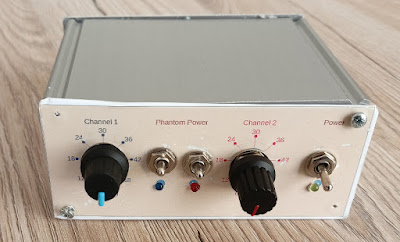
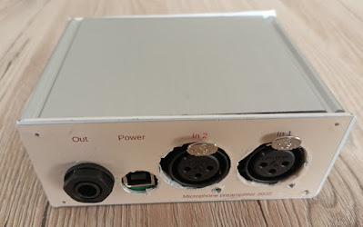
The PCB fits a standard aluminium enclosure which provides some shielding and mounting for the gain switches and additional switches and LEDs to control and indicate the presence of main and phantom power.
Labelling for the front and back panels was printed onto self-adhesive vinyl sheet:
The assembled prototype now awaits evaluation in the field.


Comments
Post a Comment