Introduction
Following on from the first part of this series of articles, we take a look at some of the design choices involved in creating an actual implementation.
Decisions, Decisions
The two candidate designs were very similar in performance, so choosing one was somewhat arbitrary. In the end, I selected the THA1510 circuit as it potentially offered better common mode rejection.
The next issue that arose was how, physically, to construct the hardware. The active circuitry itself is sufficiently straightforward that it could easily be built on strip board. However, the transformers and audio and power connectors also need a home and it seemed preferable to come up with some sort of PCB. Given that ordering one PCB typically means ordering several, I decided to create a PCB sufficiently generic to suit a number of different potential projects. You can read more about how it was created here, but it provides for two XLR connectors, two transformers, two relays (for switching), a power connection (either USB B or 4-pin DIN connector) and an audio jack (either 3.5mm or 6.35mm). The rest of the PCB is designed as a breadboard, providing flexibility at the expense of additional wiring. The size of the board was determined by the size of the aluminium case I had available to house it (10cm x 8cm).


Final Schematic
The final schematic differs very little from the prototype - the addition of some decoupling capacitors and the addition of the gain switch:

The gain available in the various switch positions is (approximately) as follows:
| 1 | 2 | 3 | 4 | 5 | 6 | 7 | 8 |
|---|---|---|---|---|---|---|---|
| 0 dB | 12 dB | 18 dB | 24 dB | 30 dB | 36 dB | 42 dB | 48 dB |
Some of the resistances are created from series pairs - this stems from a desire to use only E12 values where possible: the 39R values used in positions 7 and 8 are the exceptions.
Also to be noted is that a different "ground" is shown for pin 1 of the XLR connector - exactly what should be grounded where will be discussed in more detail in a further post on power and grounding.
Physical Layout
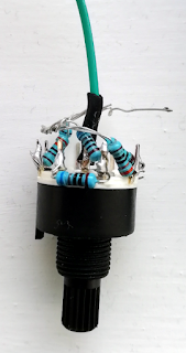
The construction can be seen in the image below:

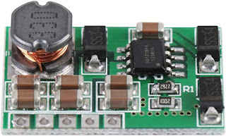
The 15-0-15V converter can be seen immediately below the 6.35mm jack socket.Rather than modify the separate DC-DC converter (right, red) with higher-voltage capacitors, I simply turned the output voltage down to around 42V to give a bit more margin: the microphones worked perfectly well on the slightly reduced supply. The switched resistor chain plugs into header pins adjacent to the IC.
For initial testing, rather than using a matched pair of resistors to feed phantom power to the XLR connector, I used a single 3k3 resistor connected to the centre tap of the input side of the transformer. More discussion of phantom power issues will follow.
Performance
In initial testing, the pre-amplifier has worked well with no obviously-audible defects. The frequency response is rather wider than I would have expected for a transformer design - the apparent ringing around the lower and upper ends of the audio spectrum seem to be a measurement artefact:

Otherwise the behaviour is inline with the observations from Part 1.
Comments
Post a Comment