Introduction
Sometime in the 60s, condenser microphones were starting to take over from rather more unwieldy ribbon microphones. There are different types of condenser microphones, but, unlike their predecessors, they all require power - and existing installations didn't provide it. Rather than rewire every studio, a means was found to deliver the required power using the same wires that delivered the audio signal (hence "phantom" as it lurks unseen on the existing wires). As it was common for studios (particularly broadcast studios) to have telephone equipment, for which 48V power is the norm, the same voltage was chosen. Unfortunately.
Phantom power is a menace. In fact it's an even bigger menace than it at first appears and may require significant mitigation. The fundamental problem is that run-of-the-mill semiconductors aren't designed to work at 48V and it all goes downhill from there as the THAT Corporation documents cited attest.
But there is more...
Basic details
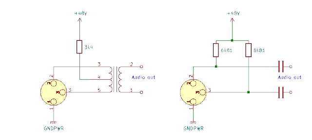
Phantom power is provided by applying +48V equally to both the differential signal lines (pins 2 and 3 of the XLR) and 0V to the third conductor present in the cable (pin 1) which is often loosely described as "ground". Of course, you can't simply connect the power supply directly to both signal lines or you'd short them out and there can't be a difference between the voltage you apply to them or it would defeat the differential nature of the signal. So what's the solution?
Actually, there are several, a couple of examples are below.
The "official" solution is to use two closely-matched resistors (they're usually specified as 6k81 to identify E48 series precision though the exact value doesn't matter as long as they're both the same), in which case you'll need decoupling capacitors to keep the power from the audio input stage (plus the additional protection discussed in the linked papers). If you have a transformer-coupled input stage you can either use the same pair of 6k81 resistors and dispense with the capacitors, or, if the transformer has a centre tap, you can in principle use a single resistor of half the value and connect it from there to the 48V supply.
Practical Considerations
Many of the problems stem from high-voltage transients that can occur when connecting or disconnecting equipment. Inevitably, pins 2 and 3 of the connector will not mate simultaneously when you plug it in. In some scenarios you may have a mixture of XLR and 1/4in jack connectors which can result in temporary shorts to ground when plugging or unplugging. Either of these can result in one signal line being at 48V and the other floating or shorted. So what are the consequences?
Resistors
The first consequence is for the power rating of the resistors: although in normal operation the phantom power is unlikely to need to source more than a few mA, the resistors have to be rated at V²/R or, if you don't want them to fry during a short, where you have 2 resistors they should really be rated at 1/2W and in the centre-tapped case a single resistor would need to be rated at 1W. Close tolerance resistors are most easily found at 1/8W and 1/4W so getting the required matching for higher-rated resistors may be troublesome. You can get some advice on resistor matching (and more) here.
Of course, if you are sufficiently disciplined not to apply the phantom power until all the connectors are in place and to turn it off before disconnecting, you may be prepared to live with the risk. You should also arrange for the output level from your audio equipment to be muted before applying the power if you want to avoid a "pop" or "thud". Some equipment designs include a "soft start" for phantom power, usually using a resistor to charge a capacitor gradually to the final voltage and discharge the capacitor through a resistor when the phantom power is disconnected. If you attempt this, remember that the initial charge and discharge current is likely to be substantial and components will have to be rated accordingly.
Capacitors
Many of the other problems relating to capacitor coupling are described in the linked papers and I won't repeat them here. Solving them not only adds to the component count of a typical audio circuit, but because of the high voltages involved and the relatively low frequency of audio signals, the physical size of the components adds significant bulk to any practical product, even compared with the bulk of an audio transformer.
Transformers
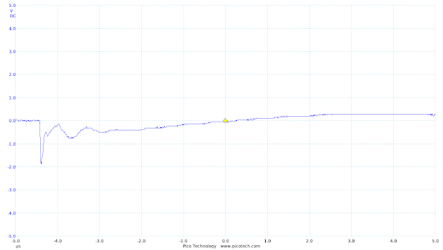
Issues relating to transformer coupling seem to have been less reported. Fortunately, audio transformers have some natural advantages over capacitors in the case of sudden voltage transients on their input: they act as a low-pass filter, flattening the spike and they saturate quite easily, reducing the energy they can transfer. I set up a transformer in a phantom power configuration and measured the output as one of the two signal lines was briefly shorted to the 0V rail. The result was this:
There was an extremely brief excursion at the output of 2V which would not be of any real concern in terms of possible damage to components in the connected circuitry. This suggests the panoply of mitigations suggested for capacitor-coupled circuits can be avoided.
There could, however, be concerns about the transformer itself. Audio transformers are not designed to handle constant DC currents: the core can become magnetised in these situations, affecting the ability of the transformer to transfer signals. This can even be a problem in the absence of any miswiring. In the case of the centre-tapped transformer above, DC current flows constantly through the winding of the transformer supplying the phantom power. If the transformer were perfect, this wouldn't matter as the magnetic field generated in the winding 3-4 would cancel out the field generated in winding 4-5. In practice, it likely won't do so perfectly, exactly how perfectly will depend on how the transformer is wound. Some are manufactured specifically to support this mode of operation, but it's probably best not to adopt this form of power injection unless the specification explicitly supports it.
Using a two-resistor solution, the worst case scenario for a short-circuit is that there will be a current of around 7mA passing through the transformer, resulting in a potential difference of 1.5V. This isn't likely to physically damage the transformer, though there could potentially be a magnetisation issue in the case of a prolonged fault. Protecting against such a situation is probably more trouble than it's worth: you'd have to detect the fault and shut off the phantom power. And, in the end, transformers can be demagnetised.
Conclusion
While phantom power can cause all sorts of problems, transformer-coupled input stages seem to have fewer compared to capacitor-coupled inputs.
While there are benefits in professional environments in having a secure source of power, particularly if you're rigging up dozens of microphones, for most non-professional purposes rechargeable batteries would probably be a much better solution for most applications. Unfortunately, phantom power, for all its drawbacks, has acquired a professional aura and "prosumer" kit seems obliged to use it, if only for marketing purposes and equipment designers seem condemned to wrestle with it in perpetuity.


Comments
Post a Comment